First design
A design is one cable assembly: its connectors, the wire between them and every joint. Everything you print, from the build sheet to the continuity spec, is derived from it. This page takes one from nothing to a build sheet.
Create it with the wizard#
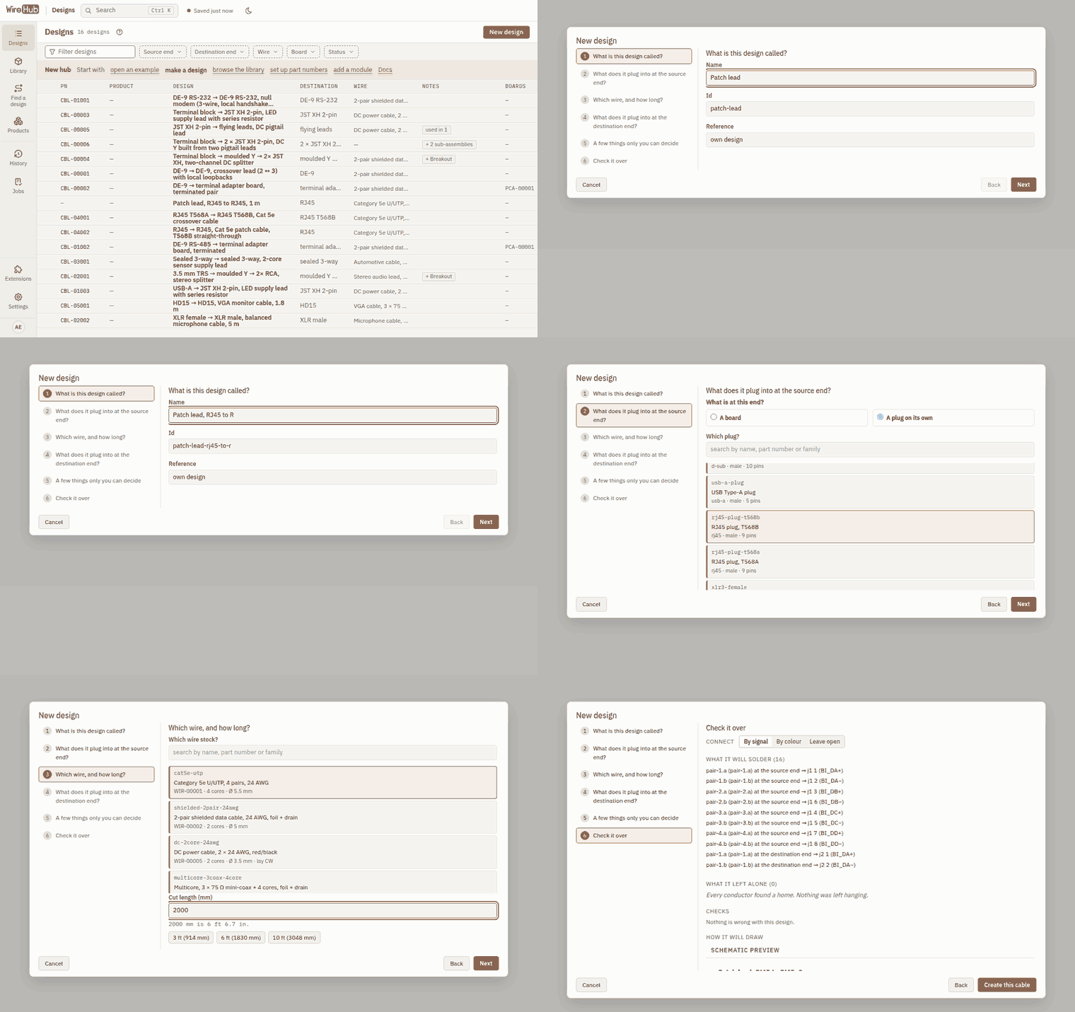
On the designs list choose New design. The wizard asks six things and only wires what the catalog states without ambiguity, so what lands on the canvas is something you could build:
- Name: what a builder reads at the top of the build sheet, and where the information comes from (the reference).
- Source end: the plug that goes into the source device, or the board the cable is soldered to.
- Wire: the stock the trunk is cut from, and its length.
- Destination end: the plug or board at the far end.
- Choices: a few things only you can decide, such as which of two landings carries a signal.
- Review: everything the wizard will connect, and what it left alone.
Wire it on the canvas#
The design opens on the Build view, a canvas with a parts palette beside it.
- Drag a connector, board, component or another design from the palette onto the canvas.
- Drag from one pin to another to make a joint. The wire model decides which conductors are available, so you connect pins and conductors, not lines.
- Select anything to edit it in the inspector: part number, colours, lengths, notes.
- Issues appear in the issues panel as you edit. An error blocks saving and releasing a version; a warning does not.
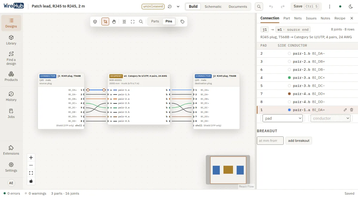
Switch to Schematic to see the same design drawn as a wiring diagram, laid out for you.
Save and version#
Save (Ctrl S) stores the design. While you edit, others see it as locked. Release a version when it is ready to build; versions are numbered snapshots you can compare and print from later.
Print the documents#
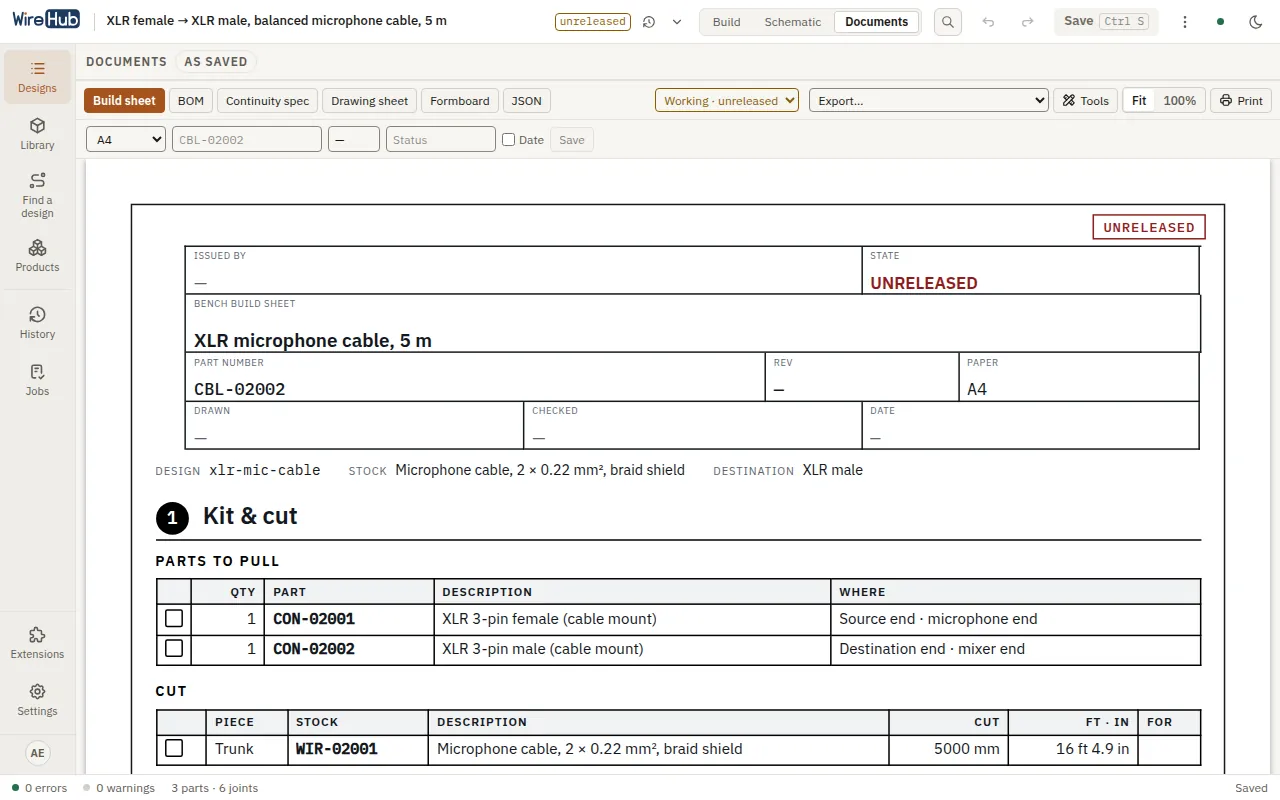
The Documents view shows what the design produces:
| Document | What it is |
|---|---|
| Build sheet | The bench flow, one page per stage: kit and cut, each end, assembly, test |
| BOM | The bill of materials, with part numbers and quantities |
| Continuity spec | What to test: connections that must exist and pairs that must be isolated |
| Drawing | An ANSI-A drawing sheet |
| Formboard | A scaled board layout |
Print produces a PDF through the browser or the optional PDF engine. Export downloads the BOM, wire list, cut list, crimp list, continuity data and wire labels as CSV or XLSX. See Exports for every format.
Next#
- Concepts: how designs, the library, packs, part numbers and the resolver fit together.
- Part numbers if your shop has a numbering scheme.